
- #ARDUINO STEPPER MOTOR CONTROL BOARD DRIVERS#
- #ARDUINO STEPPER MOTOR CONTROL BOARD DRIVER#
- #ARDUINO STEPPER MOTOR CONTROL BOARD FULL#
- #ARDUINO STEPPER MOTOR CONTROL BOARD CODE#
When switching this pin to HIGH to wake up the IC, allow 1 ms of delay before sending a STEP signal. When set to LOW, the A4988 enters sleep mode, and disables functionality of the FETs, internal current regulator and charge pump. This must be set HIGH to enable functionality of the motor driver. The translator is set to the Home state as well. When set LOW, all STEP commands are ignored and all FET functionality is turned off. See truth table below for HIGH/LOW functionality. Microstep Select 3 has a pull-up resistance of 20 kOhms. Microstep Select 2 has a pull-up resistance of 20 kOhms. Microstep Select 1 has a pull-up resistance of 20 kOhms. If set to LOW, all FETs will be enabled, allowing motor control. If set to HIGH, the FETs will be disabled, and the IC will not drive the motor. Enables the FET functionality within the motor driver. Other half of connection point for bi-polar stepper motor coil B.ĮNABLE: Logic Input.
#ARDUINO STEPPER MOTOR CONTROL BOARD FULL#
Half of connection point for bi-polar stepper motor coil B.Ĭoil B-: DMOS Full Bridge 2 Output A. Other half of connection point for bi-polar stepper motor coil A.Ĭoil B+: DMOS Full Bridge 2 Output B. Half of connection point for bi-polar stepper motor coil A.Ĭoil A-: DMOS Full Bridge 1 Output A. Board Top PinsĬoil A+: DMOS Full Bridge 1 Output B. Several pins of the A4988 IC are broken out on the Big Easy Driver, allowing direct connection to a bi-polar stepper motor, as well as a microcontroller. Functionality between the two sets does not change. You can use whichever pin connections work best for your project. The secondary connection points are closest to the edge of the board, and are spaced to fit 2-pin screw terminals.

The first, which are the pins closest to the center of the board, are spaced out to fit standard 0.1" headers. Each pin present on the board has two connection points.
#ARDUINO STEPPER MOTOR CONTROL BOARD DRIVER#
Thanks everyone, if someone needs more information i'll be posting it here.The Big Easy Driver is designed around the Allegro A4988 motor driver. I don't know if this behaviour is normal or not, i would like your opinions about that please. So i'm limited using low speeds if i want more current. I also found that while increasing the current limit i can't set high speeds. I noticed that using less current configurations the motor works perfectly, but in fact it should be possible to drive it at higher current values.
#ARDUINO STEPPER MOTOR CONTROL BOARD CODE#
Then if i run the code using a PD (Pulse Duration) of 1000 micros or whatever value, the driver stops working, a red light turns ON permanently until i switch OFF the Power Supply and tun it ON again. I configured the motor and the driver same to the torque-speed curve provided in the datasheet of the motor, I used 32V, 4.9A of peak current, and 2000 microsteps.

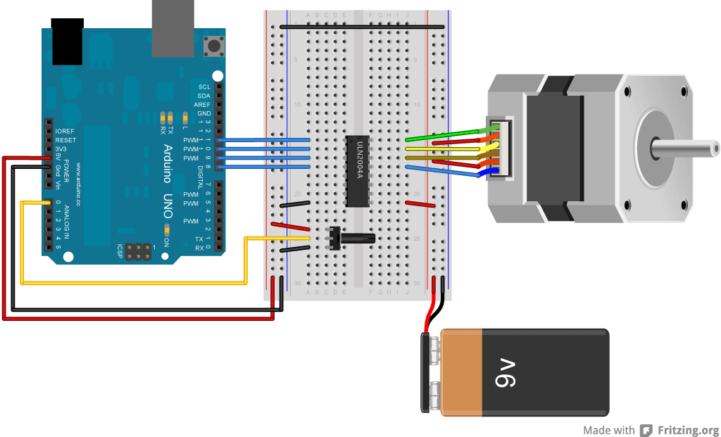
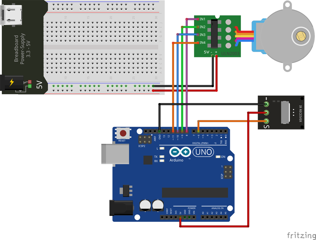
The problem is that I want to provide more current to the motor, up to 4A aprox because I want to test the max torque that can handle. So, the motor rotates 6000 microsteps, then wait 1s and repeat again. My system scheme is added as an png image. I couldn't find to much info about the motor of this particular seller but i found a similar version of STEPPER_ONLINE. So i'm using a NEMA 23, 3Nm torque, 4A of current stepper motor from the RTellingent manufacturer. My aim now is to test the maximum torque-speed limitations of the motors.
#ARDUINO STEPPER MOTOR CONTROL BOARD DRIVERS#
I'm using DM556 Stepper DRIVERS (link DM556 datasheet) and an ARDUINO uno as the controller. I recently have started trying to use stepper motors, i heard about them i knew how they work, but i'm having problems to drive them propertly. I have to design the entire robot arm, from the 3D design to the electronics system. I have knowledge of microcontrollers, basics of motors, electronics in general but i haven't tried to make projects with ARDUINO until now. I'm an Electronic Engineering Student doing it's final project. Hi everyone, this is my first post so i'll try my best.įirst of all i'll introduce myself a little bit.


 0 kommentar(er)
